Wednesday, May 26, 2010

Garden Entrances (part 2) ...This Time With a Seat

"Transition" areas in my garden signal changes. In this case, moving from the "sports court" onto the meandering garden path.

Several transitions include: going from a hard concrete surface to a crunchy "giving" surfacing (in this case, crushed rock); an opposite activity/mood change from sports activities to passive garden sights; an overhead passage from mostly airy sky into the heavy shade of trees; a mood change from the square-cut, somewhat formal structured/active to the passive/casual that includes a seat upon which to rest; moving from open-air (and somewhat sparse) area to an enclosed area filled with "eye candy"; and finally, the accent/mood color transition from a cheery yellow to a contemplative lavender.

All this is signaled in the entry structure which leads one through these changes. Similarly, when moving in the opposite direction, the entry structure becomes an exit-from-the-garden structure, again signaling a change in mood or activity.

Advantages created by the built-in seating include: 1) safe, yet close, observation of sports activities, or 2) a place to rest and wait your turn at such activities, 3) an invitation to relax, 4) potential for a romantic interlude, 5) a secret get-away spot to read a book, or 6) just a private place to hang out away from the crowds.

I started with a rough plan which I modified several times. I didn't use bolts, instead opting for 3-inch decking screws throughout. This is my highly modified plan:


The overall construction is similar to the 6-post entry (see Garden Entrances part 1), but this entry uses only three posts. And, because there is no "ceiling," I also opted for diagonal bracing, which matches the bracing on an adjacent water craft screen.

Construction of the framework:

I first dug three holes for the outside posts and measured the distances between them and across from each other before leveling and backfilling with dirt. The width of the crushed rock path was one determining factor and another was a very large tree root, which limited the distance to the third post and the length of my entryway seat.

With posts in place and leveled, I placed 18-inch extensions on the tops of these three posts and leveled the three tops to each other. I used temporary scabbing to hold each extension to its post.

An extension is on top of the post and a temporary scab board holds it to its post.

I trimmed the ends of the entry 2 by 8 cross beam ends to match the others in the garden.

Cut block from a beam end is used as a template for the end-of-beam cut-outs.

Using my level, I ensured that the third post top was level with the other pair (I cut this extension a little long for use as the base for a birdhouse).

I added horizontal temporary scabs to keep the 2 by 8 beams level before fastening these to the extension tops. I used three-inch decking screws to fasten twin 2 by 8 8-foot beams over the entryway.

Temporary horizontal scab is in place to keep the beam level on the post for fastening.

With the cross beams secured, I removed the beam scab boards and then cut 2 by 4 "supports" for each post and mounted these to all the outside post edges to permanently cover the splices. These supports extended approximately 4 to 5 inches below the splices and are fastened with decking screws.

Mounting 2 by 4 beam "supports" to the posts.

I centered and leveled a permanent beam nailer block on the center beam to provide a fastening surface for the connecting beams to the third post. One end of the two connecting beams was cut square and the other end was cut to match the ends of the entry pair. See the sequence in the pictures below.

Aligning the permanent nailer with a level.

Permanent 2 by 4 nailer fastened with 3-inch deck screws.

An inside view of cross beams where they join the central post.

Outside view of those same cross beams.

I then cut 4 by 4 diagonal "brackets" from a spare 4 by 4 post to add stiffness to the structure. Again, I used three inch decking screws for fastening.

4 by 4 diagonal stiffener shown covering a portion of the splice point.

With the splices covered, I removed all temporary scab blocks and added the remaining "support" blocks to each post.

Each support was individually measured and cut so they met at the same point all around the post. Each outside post has three supports and the central post has two supports and two diagonal brackets.

All the 4 by 4 diagonal stiffeners and 2 by 4 "support" blocks are in place.

Since there is no 2 by 4 top to this entry arbor the main beams act as a top.

Bench construction follows:

First I determined a comfortable seat angle by sitting in some chairs at home. I then constructed this simple 2-board, 1-bolt jig and tightened the nut when I discovered the perfect angle.

Homemade angle jig adjacent to my right angle framing square.

I used 2 by 4 pressure-treated stock to cut the seat bottoms to length and 2 by 6 pressure-treated stock to cut the seat backs. The seat backs were run through a table saw to achieve a taper at the top and greater width at the bottom. To get matching pairs, I temporarily screwed two 2 by 6's together.

Work pieces screwed together and then sawn at an angle.

They didn't all turn out exactly alike (I needed three backs per seat), so I placed three together and hand planed them.

Hand planing the back supports to make them equal in size.

Using the seat angle jig, I determined that each seat back support piece needed a 3 degree angle cut off the wide (bottom) edge.

Saw set for 3 degree angle cut on bottom of seat back support pieces.

The seat bottoms were contoured with a band saw (a jigsaw would also work for this step). Then the back and seat supports were primed and painted.

I assembled each seat back and seat bottom pair and drove in decking screws from both sides. Because the outside pairs of seat backs would be attached to the inside edges of their support posts, these were assembled as opposites.

I added an overlength 2 by 4 to the bottom backside to create a framework assembly and carefully screwed the support pairs to it to make a "snug" fit between the posts. The extra length would allow an additional screw to hold the framework to the post. It was probably overkill, but I like my seating to be solid.

I also added stiffeners at a point near the front of the seats. These stiffeners were staggered so I could drive in the decking screws. I repainted any areas that were bare and also covered the screw heads.

Close-up of the staggered front-of-seat stiffeners.

When the completed framework was dry, I mounted it loosely between the posts and leveled the seat at 16 1/2 inches off the ground. With the seat slats installed, it will be approximately 17 inches off the ground, a comfortable height for most adults.

Measuring seat height above the ground.

Checking level and then fastening the rear seat frame 2 by 4 to the post. Note the added length of the 2 by 4 at the back.

I measured the arm rests as I held them against the post and the in-place back frame and cut out a pair of arm rests from 2 by 6-inch stock.

Two by 6-inch stock cut for matching arm rests.

The arm rests were clamped in place to check the fit and a bottom support angle was cut from a 2 by 4 to meet under the seat on the post and under the arm rest while it was still level.

These pieces were then primed and painted before assembly.

Primed arm rests and one arm rest support.

Each arm rest was clamped and checked for level (again) before fastening to its corresponding post.

Right hand arm rest leveled and ready to screw into post.

The support braces were then attached to the arm rest, the post, and the seat frame.


Left hand arm rest in place with support brace in place beneath it.

The seat and back slats were primed and painted after I made cut-outs where the support braces intersected the seat and where the arm rests intersected the seat backs.

Painted seat slats awaiting installation.

The seat slats were attached to the framework and all exposed wood and screw heads were painted.

Slats added to seat and back.

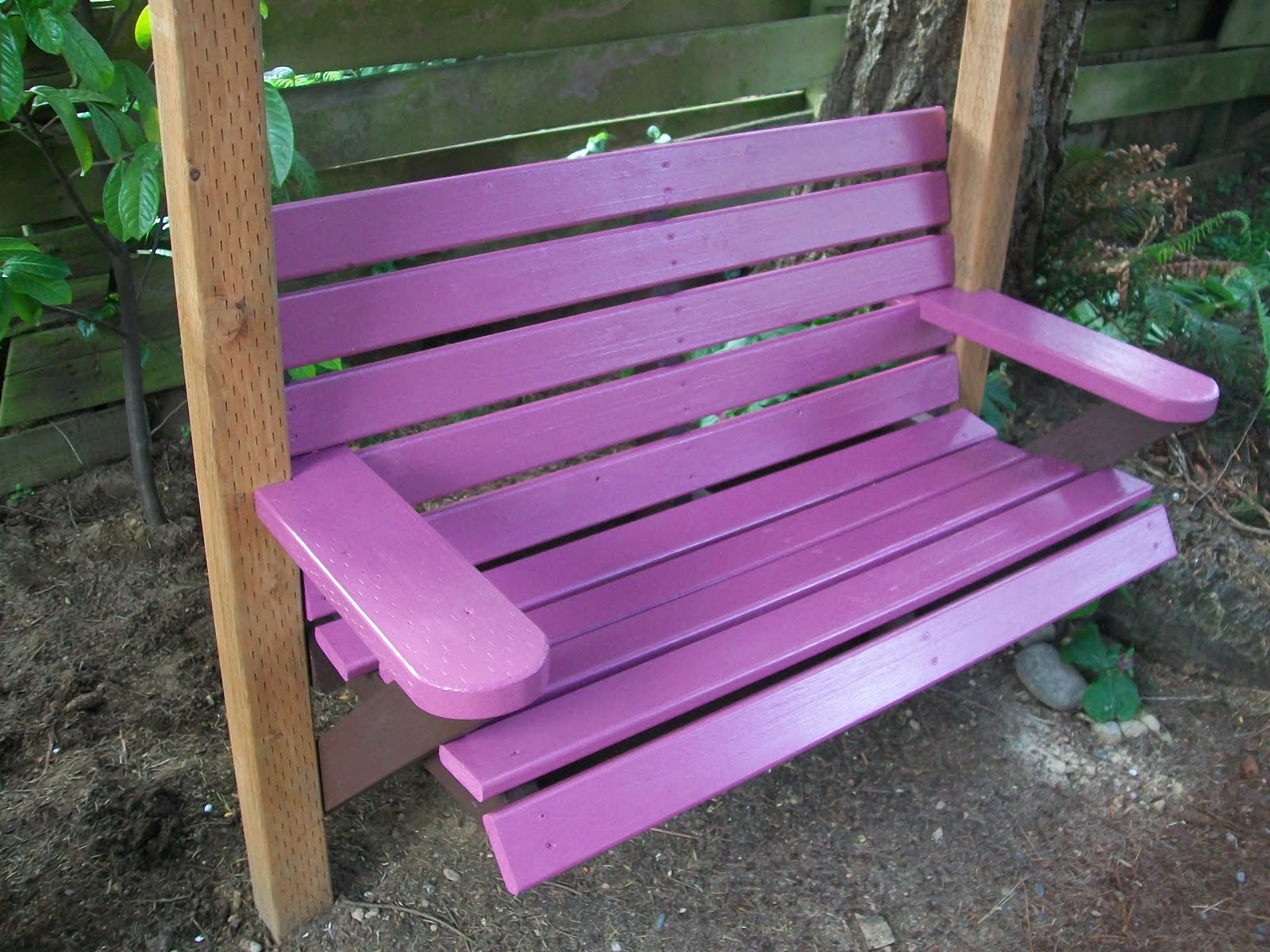
The completed entry seat.

The completed entry.

New Garden Inhabitant?

I didn't know if I should post this and considered waiting. But I need feedback, so...I'm posting it here and would like to know what others think and what I should do (if anything). And no, I'm not some old looney-tune. (At least not in MHO.)

A little background...my wife and I went for a trip to Pennsylvania to witness middle son's college graduation and do some sight-seeing. We were gone for ten days. My other two sons were at home, but say they didn't go into the backyard, and they claim they don't know ANYTHING.

I looked at my garden and noticed a bit of color that I hadn't expected to see. I got closer to investigate and took these pictures.

That brown object next to the tree trunk is a "tiny" house, barely larger than a bird house and is complete with door (that doesn't seem to open--no handle and appears to be stuck and window opening with shutters.

This is a side view showing the window opening.

This colorful fence is what first caught my eye from our back deck.

I shined a flashlight in the window, but couldn't see a thing. The door doesn't open, so I don't know if this "house" in my yard is inhabited.

Stranger things have happened to me, but nothing comes to mind immediately.

WELL...a new wrinkle has emerged since my last post on this subject.

Here is the latest development.

Thursday, July 23, 2009

Garden Entrances (part 1)

Garden entryways are important for a number of reasons: entryways contribute to the overall structure of the garden and are the first indicator of the garden style; an entryway transitions between the inside of the house and the outside, or transitions between the public grounds and private grounds or between garden rooms.

Entryways may act as room dividers. For example, an opening in a low hedge to separate a kitchen garden from the flower cutting garden, or an expanse of lawn separating the natural (e.g., wildlife) area from the formal (e.g., dining) area. Other entryways may separate sports courts, sunbathing, shady relaxation, and child play areas, etc.

Entryways may be supplanted by transition areas, in an open garden. Expanses of lawn, low fences, and planting separations (use of borders, berms, shrubs or trees) can also act as transition features.


The construction looks fancy, but isn't. In fact, it is quite simple, the hardest part is digging the six post holes so that they align properly.

Construction details follow:

I first dug post holes for the four outside posts and measured the distances between and across from each other before leveling and backfilling with dirt. Next, I placed the intermediate posts between the outside posts and leveled them. I did not pay particular attention to the height of each post because I would deal with that detail later, but each post was sunk approximately 24 inches into the ground.


The posts line up in a row on both sides of the entry arbor.


With the posts (pressure-treated 4 by 4's) aligned in a row and across from one another, I measured their overall out-of-ground lengths and cut another 8-footer to add another 18 inches to the shortest post. This additional piece placed at the top of this post put the total height at 7+ feet. I scabbed a length of scrap to both the post and post extension to temporarily hold the two together.


Post with extension and scab board holding it together.

I did the same for the opposite post, but used my level and measured and cut the extension piece to ensure that the tip tops were level to each other. I continued this process for the other outside posts and their extensions and then measured and cut lengths for the intermediate posts extensions ensuring that they, too, were level with the outside posts. All posts and extensions were temporarily scabbed together and held vertical with scrap wood.

I trimmed the outside main beams (2 by 8's) to match the grape arbor cuts and mounted these beams to each set of three in-line posts. I used three inch decking screws for fastening the beams to the post extensions. Once the outside beams were fastened in place, I attached the inside 2 by 8 main beams in similar fashion ensuring that the ends of all the beams aligned with their post mates.

I then cut both 2 by 4 and 2 by 6 "brackets" to cover the splice points between the posts and their extensions. Each beam bracket extended from the bottom of each beam to approximately 4 to 5 inches below the splice point. These were the 2 by 6's. Again, I used my level to ensure that the bottoms all matched up. I used three inch decking screws for fastening.


Two by sixes "support" the main beams.

With the splices covered, I removed the temporary scab blocks and finished the remaining sides of each post using 2 by 4 brackets to extend to the top of each post and align with the 2 by 6 brackets on the other sides of each post. The only tricky measuring was where the 2 by 4 brackets extended to the top of the beam instead of the bottom of the beam. Each 2 by 4 bracket was individually measured and cut so it met at the same point below the top of the post. This was to ensure that the "top beams" would meet at the tops of these brackets.


Two by fours meet at the top of the post and "support" the ceiling boards.


The top beams consist of untrimmed 2 by 4 by 8-foot long pressure-treated boards lying atop the main beams and these were fastened (in pairs) to both sides of each of the six post tops for a total of six. An additional two sets of pairs were placed between the posts to achieve a fuller look to the "ceiling." These additional pairs will be fastened to scrap 4 by 4 stubs cut to a length long enough to also five surface area to fasten them to the main beams.

The completed Garden Entrance is shown below.


Entry view.


Side view.

Thursday, June 11, 2009

Raised Garden Bed and Rock Wall

Sometimes, one project begets another. I like that, actually, because it keeps the creative juices flowing and presents its own sets of challenges. I had several problems to solve.


Problem 1: Overestimating material requirements. My pond project left me with a substantial pile (2 feet wide, 8 feet long, and 1 foot high) of leftover gravel and rocks (up to 4 inches in diameter). I needed a place to temporarily store this excess rock. (It was crowding our driveway, where we parked four cars.)

I decided the 30-inch wide bare earth strip between the south fence and the sport court could serve as a temporary storage area.


Problem 2: Too much mulch. I already had a large mulch pile that I'd moved close to the north side fence. I'd subsequently covered it over with garden soil and planted potatoes in it. I needed space for the gravel and rock, so I expanded the large mulch pile with excavated dirt from alongside the sport court.

I created a 3-foot tall 8-foot diameter green mound
where the worms could play and my potatoes could grow.

Problem 3: Bishop's weed (aka goutweed) takeover. Ev
er make a gardening mistake? I thought Bishop's weed was pretty--and because it was free, (came through a back fence) I'd allowed that weed to take over a 30-inch wide strip of bare earth next to our sport court. Only later, did I learn the name of the plant. Note: Be suspicious of anything with 'weed' as part of its name.

In the process of uprooting the Bishop's weed a year later, I harvested a couple of huge black plastic bags of the stuff. Don't even consider using it as mulch--takes too long to break down--put it in the trash! I dug deeply enough to completely remove all traces of its invasive roots.


I did move the excavated dirt from the 30-inch-wide strip over to the growing mulch pile and dumped my rock and gravel into the excavated strip beside the sport court. Temporary rock storage problem solved.


Rock and gravel is temporarily stored next to sport court (the dirt mound at bottom right was contributed by Mr. Mole)

A year later, I harvested the potatoes growing in the m
ulch pile, but the tall earth/mulch pile was an unsightly mound in winter. I needed to spread it around a bit. That's when I first contemplated a permanent raised bed.

Problem 4. Rotting fence boards. I knew I couldn't spread the
earth/mulch all the way to the fence, which was already rotting at the bottom from a long-term buildup of organic materials on both sides. I could solve that by purchasing new fence boards, but I had to consider how to protect the replacement fence.

My answer was both simple, economical, and involved the least labor for me: concrete building blocks.

I laid up two courses of concrete building blocks as the back wall of the new raised bed. Concrete blocks aren't pretty. However, my back-of-the-raised-bed block wall is mostly hidden from view by both the dirt in the bed and the plantings growing in the raised bed. The back-of-the-raised-bed wall is fairly close to the wooden fence, but there's still plenty of space for good air circulation at the bottom.


Concrete blocks help keep dirt in the bed and away from fence. Note air gap between fence and blocks.

I had a few large rocks leftover from the pond project and used them to start the front-of-the-raised-bed wall. My block back wall is 12 inches tall and the rock front wall is just slightly shorter.

Completed rock wall with gravel path in front.

Bug's eye view of wall and gravel path.

Problem 5: Digger dog. Our dog likes to dig (surprise, surprise). My son pointed out to me (the day after my rock wall was up) that Cookie dog had dislodged the rocks in a section of the wall. She'd dug in front of and beneath the wall rocks and undermined them. (Seems she was after an invader--a mole.)

To prevent her undermining my rock wall again, I laid down a pathway of compacted gravel in front of the new rock wall. This won't stop her from digging within the raised bed, of course, but my new rock wall is reasonably safe.

Problem 6: Mole. Since Mr. Mole travels from my yard to the neighbors yard and back, it isn't a serious problem for the moment. I'll probably have to trap it (...squish...).

Wishing Well (part 1)

A Look at the Space Between the Raised Bed and the Wood Fence.

A portion of the front of the rock wall.

End of the Rock Wall and Start of the Wishing Well.

A Peek Inside the 'Dry' Wishing Well.


Why build a wishing well? I've been asked that by several family members. I don't have a really good answer, it's just that I want to build one, I have the space for one, and I'm enchanted by the sight of them (especially since visiting Colonial Williamsburg in 1999).

There is a sense of mystery with wishing wells. Seeing one, I ask myself, is there water? Is it potable water? What's it taste like? How deep is it? I want to look inside. And, if no one is looking, maybe drop a marble or a pebble inside and count the seconds till I hear a 'plop?'

Mystery and wonder is WHY I wanted to build a backyard well. Not a real one. No hole in the ground. I only wanted to simulate a wishing well. I found plans at Buildeazy for a wooden wishing well, but it didn't appear as large, or as subtantial, or as 'real looking' as I'd like. I did like their plans for a wood bucket and windlass though (crank for bringing up the bucket and rope), and I may eventually build a similar one.

I used concrete building block material because: it is cheap, substantial, easy to use, won't blow over in a wind, and it fit in with my plan for a raised garden bed. It took three trips to The Home Depot with my Ford Explorer to bring all the needed blocks home (for the raised bed and the wishing well).

Monday, June 8, 2009

Garden Accessory Projects (part 3)

FENCE-MOUNTED PLANT CONTAINER SHELVING.

This plant container shelf system uses the strength of the fence (including fence rails and fence posts) to support gallon-sized plant containers. It has several advantages. This system foils our Northwest slugs who cannot find their way up to the plant shelving. This system does not use up any precious ground planting space. And the container plants get plenty of air circulation, thus promoting healthy living conditions.

First, I assume that all fence rails have been installed vertically (that is, the nominal 4 inch portion of the 2 by 4 rail is mounted vertically), using fence clips to attach them to the fence posts. Otherwise, you'll have to adapt to your current fence system.

The "support system" consists of several wood Rail Supports (minimum spacing of the rail supports is 3 feet apart). The Rail Supports in turn support the Shelf Brackets. The length of each rail support is determined by the spacing between the existing fence rails. Each Rail Support is notched to fit over the fence rails and end up being flush with the fence boards. The Rail Supports are fastened to the fence rails with 3-inch decking screws.

The shelf Support Brackets are scrap pieces of 2 by 4 cut to the width of the desired shelving. These are fastened to the Rail Supports with decking screws.

The "shelves" are lengths of lath loosely resting on the Support Brackets. The weight of the plant containers holds the lath strips in place. You could also use a couple of 1 by 4's, or 2 by 4's for the shelves. The Support Brackets will hold a lot of weight, so use 2 by 4's or larger stock.


Sketch of a fence 'rail support' and 'shelf bracket' to hold plant containers


The completed fence plant container shelving.


Mounting detail (a Support Bracket is mounted to a rail support)


Mounting Detail (the Support Bracket on the right is screwed to a fence post)


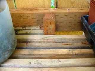
Rail Support board is notched and screwed to fence rails (top and bottom)


HYPERTUFA ITEMS.

I read a book about creating items from hypertufa and decided to try my hand using this medium. I first made a hypertufa planting trough using a cheapo styrofoam cooler for my mold. (The cooler wasn't being used because the lid got crushed. I like to recycle quasi-useful stuff.) I also had some left-over galvanized hardware cloth (1/2-inch by 1/2-inch spacings) that I used as reinforcement. Before applying the 'tufa' mixture to the upside down cooler, I punched two large drainage holes in the styrofoam bottom and made sure there were holes in the hardware cloth at those points. The main advantage of hypertufa is it is comparatively light weight, so moving the completed items is relatively easy. The disadvantages of using hypertufa is the LONG drying time. It will be several days until you can move the project, and a week before you can use it for its intended purpose. You'll also need a pair of tin snips to cut the hardware cloth and gloves for mixing and applying the hypertufa mix. I used wire to hold the metal cloth together in the curves and cut areas. You can use bottle caps to act as spacers between the hardware cloth and the syrofoam ice chest or anything else you may have handy. Just be sure the hardware cloth doesn't show through and that the tufa contacts the styrofoam inside the metal wires. The drawing below shows the process.


Components to create a Hypertufa Trough


Completed Hypertufa Trough with plants.

The photo shows the completed item (one year later). I used the left-over mix to make peek-a-boo 'critter' faces that are placed elsewhere in the garden.

Garden Hypertufa 'critter' with large marble 'eyes'